Tầng 8, Tòa nhà Sannam, số 78 Phố Duy Tân, P.Dịch Vọng Hậu, Q. Cầu Giấy, Tp. Hà Nội, Việt Nam

Advisory
Direct: 0904565626
Advisory
Direct: 0904565626
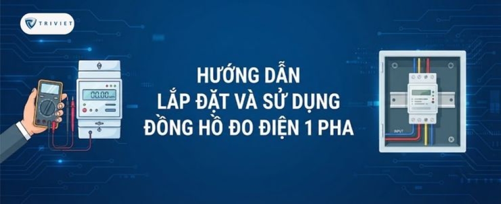
Guide to Properly Installing and Using a Single-Phase Energy Meter, from Wiring and Testing to Reading Parameters and Troubleshooting
Single-Phase Energy Meter helps monitor parameters such as voltage, current, power, and energy consumption of an electrical circuit. However, to ensure accurate measurement and stable operation, the device must be installed according to the correct wiring diagram, with the appropriate rated specifications selected and carefully checked before power is applied.
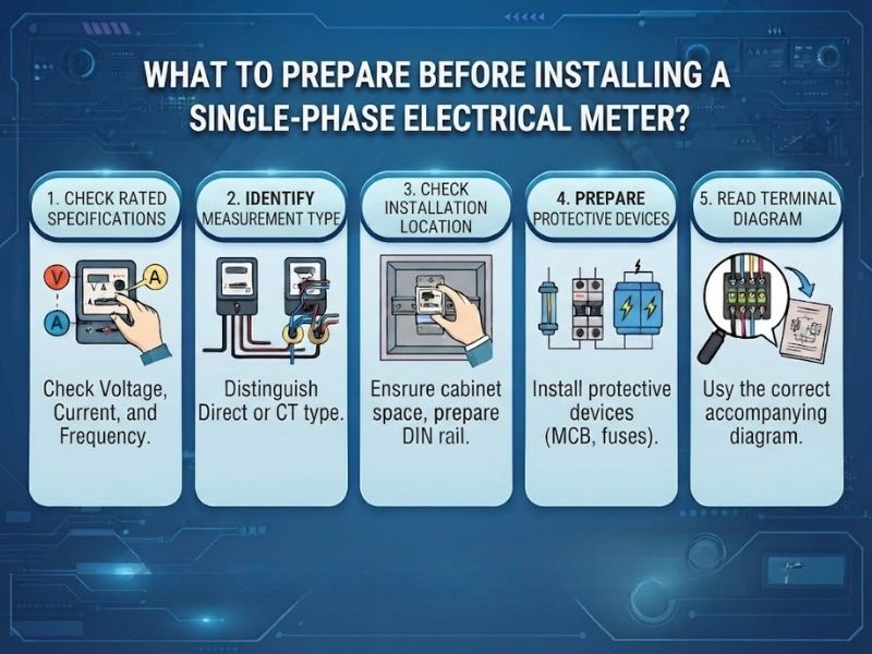
Before installing a single-phase energy meter, both the device specifications and the actual conditions of the electrical panel should be checked to ensure safe and accurate wiring.
- Check the rated specifications: Compare the voltage, frequency, maximum current, and wiring method of the meter with the electrical circuit to be measured.
- Determine the measurement method: Check whether the meter is a direct-connected type or uses a current transformer (CT), as the wiring diagrams for these two types are different.
- Check the installation location: For DIN rail-mounted meters, make sure the electrical panel has sufficient space and that the rail meets the required standard; many single-phase meters are designed for installation on 35 mm DIN rails.
- Prepare protective devices: The measurement circuit should have an appropriate protection solution according to the system design and the manufacturer's instructions.
- Read the terminal diagram: Do not connect wires based solely on the terminal numbers of another model; always use the wiring diagram supplied with the specific device.
Wiring work involving mains voltage must be performed by qualified personnel. Before working on the circuit, the power supply must be isolated and the circuit must be confirmed to be de-energized; manufacturers' installation instructions also specify this requirement.
>>> Learn more about what a single-phase electric meter is?
After identifying the correct model and terminal diagram, proceed with the installation according to the device's connection principles.
For direct-connected meters, clearly distinguish between the incoming power side and the outgoing load side according to the markings on the device. Some models have separate terminals for L-in, L-out, N-in, and N-out; for example, a DIN rail-mounted meter from Perry Electric provides separate input and output terminals for the phase and neutral wires.
The phase wire L and neutral wire N must be connected to the terminals specified by the manufacturer. Do not assume the terminal positions, as the number of terminals and wiring diagrams may vary between different meter models.
After completing the wiring, check that all wire connections are secure, the polarity is correct, and all connections correspond to the wiring diagram of the specific model before switching on the power. Checking the connections before applying power helps minimize the risk of incorrect wiring and equipment damage.
Once the wiring is complete, the device should not immediately be put into long-term operation. Instead, its display status and initial measured values should be checked first.
After applying power according to the correct procedure, the meter's display or status indicator should operate as specified by the manufacturer. Many electronic energy meters use an LCD screen to display measurement data.
The displayed voltage, current, and power values can be compared with the actual load conditions to detect incorrect wiring or abnormal parameters at an early stage.
Some meters provide current direction or operating status indicators; therefore, these indicators on the display should be checked before the device is officially put into operation.
.jpg)
Once properly installed, users can monitor the parameters directly on the display or through a communication interface if the device is equipped with communication functions.
Voltage and current provide a quick assessment of the operating condition of the electrical circuit, helping identify abnormal fluctuations during operation.
Power reflects the load level being used at a given moment, while energy consumption is usually accumulated and displayed in kWh to monitor consumption over time. Some meters also provide additional data on reactive power, power factor, or frequency.
For models equipped with RS485/Modbus, measurement data can be transmitted to monitoring systems or BMS/SCADA. In this case, the device address, baud rate, parity, and other communication parameters must be configured correctly according to the manufacturer's technical documentation.
Some errors may occur immediately after installation or during operation, especially when the wiring does not follow the correct diagram.
Possible causes may include the power supply, incorrect terminal connections, or an actual voltage outside the device's operating range. The power supply and wiring diagram should be checked before proceeding with further troubleshooting.
Check the wire connections, actual load, device configuration, and measurement method. For meters using a CT, special attention should be paid to the CT wiring and current direction according to the manufacturer's instructions.
This is an error that should be avoided from the beginning because it may cause inaccurate measurements, failure to display data, or even equipment damage depending on the device design. The solution is to disconnect the power and check each terminal against the device's official wiring diagram.
If the meter has RS485 but the system cannot receive data, check the device address, baud rate, parity, communication cables, and register configuration according to the technical documentation. Meters with Modbus typically provide dedicated communication settings and a register table.
Using the correct device and carrying out regular inspections will help ensure the reliability of the single-phase energy meter during operation.
- Select the correct rated current: Do not use a meter beyond the voltage or current limits specified by the manufacturer.
- Install it in a suitable electrical panel: Make sure the device is securely mounted and that the available space and environmental conditions meet the technical requirements.
- Keep the terminals securely connected: Check the condition of the wires and terminals during maintenance to minimize the risk of poor electrical contact.
- Monitor abnormal parameters: Any unusual fluctuations in voltage, current, or power should be investigated rather than ignored.
- Perform maintenance according to the manufacturer's instructions: The inspection interval depends on the model, environment, and level of use; the technical documentation for the specific device should always be prioritized.
Single-phase energy meters are a useful solution for monitoring voltage, current, power, and energy consumption in residential electrical systems and construction projects. To ensure accurate operation, it is necessary to select the appropriate specifications, wire the device according to the wiring diagram of each model, and carefully check the system before putting it into operation. If you need advice on single-phase energy meters or solutions for electrical measurement and energy monitoring, Tri Viet Controls can support you in selecting suitable equipment and an integration solution that meets your actual requirements.








Please leave your information, we will contact you to complete the order!